Interlock Hose Insert × SAE 6000 Flange
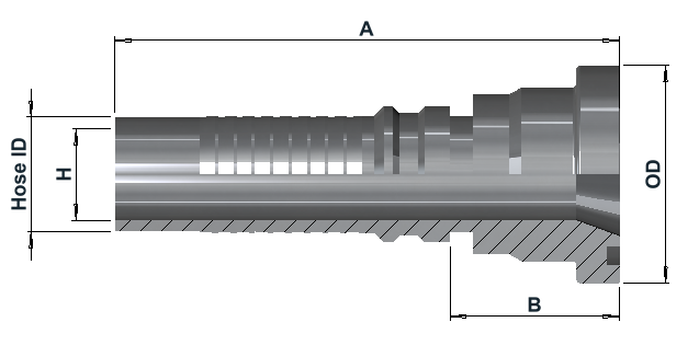
Dimensions & variants
Dimensions in mm
| Item number | Hose ID | DN | SAE 6000 | A | B | OD | H |
|---|---|---|---|---|---|---|---|
| IL28001212316 | 3/4" | 20 | 3/4" | 112 | 50 | Ø41.3 | Ø14 |
| IL28001616316 | 1" | 25 | 1" | 122 | 50 | Ø47.6 | Ø19 |
| IL28002020316 | 1 1/4" | 32 | 1 1/4" | 146 | 58 | Ø54 | Ø25 |
| IL28002424316 | 1 1/2" | 40 | 1 1/2" | 154 | 61 | Ø63.5 | Ø31 |
| IL28003232316 | 2" | 50 | 2" | 171 | 73 | Ø79.4 | Ø42 |
Article number structure
IL2800 | 12 | 12 | 316Series | Hose size code | Flange size code | Material
Product specifications
| End 1 — Hose connection | End 2 — Flange connection | General product information |
|---|---|---|
|
|
|
Technical info
Hose end
Interlock insert intended for four- and six-spiral hydraulic hoses with the matching Interlock sleeve series listed above, subject to verified hose, insert and ferrule compatibility. Requires both external and internal skiving to the specified lengths and depths without damaging the wire reinforcement. Use a matching Interlock ferrule and the validated assembly and crimping specifications for the actual hose type and size. Assembly working pressure must not exceed the lowest component pressure rating, with applicable temperature and service derating taken into account.
SAE flange end
Code 62 flange connection to ISO 6162-2 / SAE J518, sealed by an O-ring between the flange head and mating port face. Use matching flange clamps, fasteners and an O-ring suitable for the fluid and operating temperature. Assemble and tighten to the applicable specifications. The SAE 6000 designation identifies the flange series; the allowable assembly working pressure remains subject to the component ratings and service conditions.